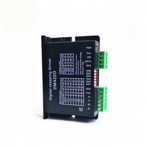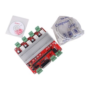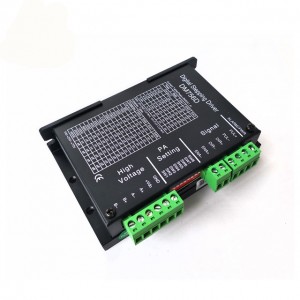
DM542 DC 24V-50V 0~4.2A stepper motor driver
BOBET specializes in small and medium-sized motor, micro-intelligent motor and new special motor design, manufacture and sell. Mainly products include the reduction motor, brushless motor, stepper motor, bus-communication motor, cluster motor, Ring full magnet motor, driver and controller and related intelligent electric products.
Bobet-Both benefit
Innovation, sharing and growth is our company’s cultural foundation. we want to be the most popular, intelligent and charity group based on our culture ,products and service.
DM542D
Stepper Motor Driver Specification
Overview
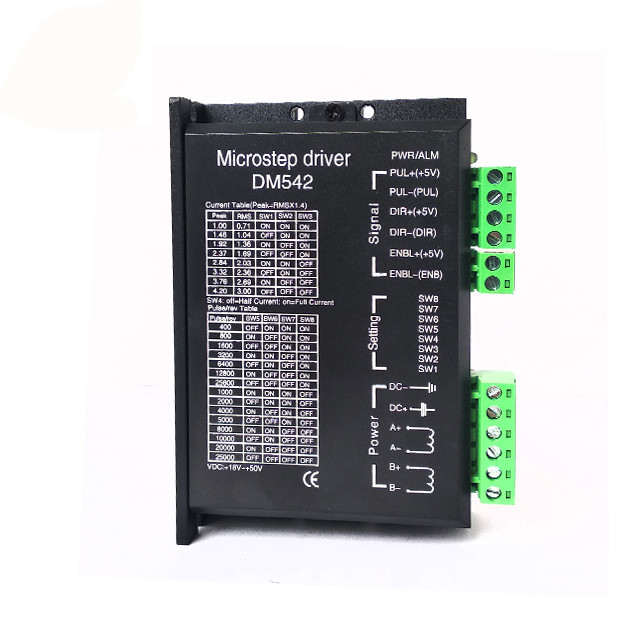
The DM542D is a new generation high-performance digital stepper driver based on DSP with advanced control algorithm. The motors driven by DM542D can run with much smaller noise and much less vibration than other drivers in the market. The DM542D possess the feature of lower noise, lower vibration, and lower heating. The DM542D’s voltage is DC 24V-50V. It is suitable for all the 2-phase hybrid stepper motor whose current is less than 4.2A.There are 16 kinds of microstep of DM542D. The maximum step number of DM542D is 51200 steps/rev (microstep is 1/256 ). Its current range is 2.1A-4.2A, and its output current has 8 stalls. DM542D has automatic semi-flow, over-voltage, under voltage and over-current protection function.
Current selection
|
Peak |
RMS |
SW1 |
SW2 |
SW3 |
|
1.00A |
0.71A |
on |
on |
on |
|
1.46A |
1.04A |
off |
on |
on |
|
1.92A |
1.36A |
on |
off |
on |
|
2.84A |
2.03A |
on |
on |
off |
|
3.32A |
2.36A |
off |
on |
off |
|
3.76A |
2.69A |
on |
off |
off |
|
4.20A |
3.00A |
off |
off |
off |
Microstep selection
|
Pulse/Rev |
SW5 |
SW6 |
SW7 |
SW8 |
|
400 |
off |
on |
on |
on |
|
800 |
on |
off |
on |
on |
|
1600 |
off |
off |
on |
on |
|
3200 |
on |
on |
off |
on |
|
6400 |
off |
on |
off |
on |
|
12800 |
on |
off |
off |
on |
|
25600 |
off |
off |
off |
on |
|
1000 |
on |
on |
on |
off |
|
2000 |
off |
on |
on |
off |
|
4000 |
on |
off |
on |
off |
|
5000 |
off |
off |
on |
off |
|
8000 |
on |
on |
off |
off |
|
10000 |
off |
on |
off |
off |
|
20000 |
on |
off |
off |
off |
Default: The pulse can be customized according to customers’ requirements.
Common indicator
|
Phenomenon |
Reason |
Solution |
|
The red indicator is on. |
1. A short circuit of motor wires. | Inspect or change wires |
| 2. The external voltage is over or low than the driver’s working voltage. | Adjust the voltage to a reasonable rang | |
| 3. Unknown reason | Return the goods |
Applications
It can be applied in a variety of small scale automation equipment and instruments, such as labeling machine, cutting machine, packing machine, drawing machine, engraving machine, CNC machine and so on. It always performs well when it is used in equipment which requires for low-vibration, low-noise, high-precision and high-velocity.
Driver functions descriptions
|
Driver function |
Operating instructions |
|
Output current setting |
Users can set the driver output current by SW1-SW3 three switches.The setting of the specific output current, please refer to the instructions of the driver panel figure. |
| Microstep setting | Users can set the driver Microstep by the SW5-SW8 four switches. The setting of the specific Microstep subdivision, please refer to the instructions of the driver panel figure. |
|
Automatic half current function |
Users can set the driver half flow function by SW4. “OFF” indicates the quiescent current is set to half of the dynamic current, that is to say, 0.5 seconds after the cessation of the pulse, current reduce to about half automatically. “ON” indicates the quiescent current and the dynamic current are the same. User can set SW4 to ”OFF”, in order to reduce motor and driver heating and improve reliability. |
|
Signal interfaces |
PUL+ and PUL- are the positive and negative side of control pulse signal; DIR+ and DIR- are the positive and negative side of direction signal; ENA+ and ENA- are the positive and negative side of enable signal. |
|
Motor interfaces |
A+ and A- are connected to a phase winding of motor; B+ and B- are connected to another phase winding of motor. If you need to backward, one of the phase windings can be reversed. |
|
Power interfaces |
It uses DC power supply. Recommended operating voltage is 24VDC-50VDC, and power consumption should be greater than 100W. |
|
Indicator lights |
There are two indicator lights. Power indicator is green. When the driver power on, the green light will always be lit. Fault indicator is red, when there is over-voltage or over-current fault, the red light will always be lit; after the driver fault is cleared, if re-power the red light will be off. |
|
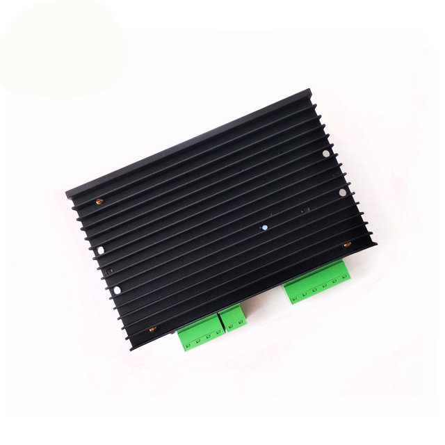
Installation instructions |
Driver dimensions:118×75×32mm, please refer to dimensions diagram. Please leave 10CM space for heat dissipation. During installation, it should be close to the metal cabinet for heat dissipation. |
Signal interface details:
The internal interface circuits of the driver are isolated by the opt coupler signals, R in the figure is an external current limiting resistor. The connection is differential. And it has a good anti-jamming performance.
Control signal and external interface:
|
Signal amplitudes |
External current limiting resistor R |
|
5V |
Without R |
|
12V |
680Ω |
|
24V |
1.8KΩ |


,planetary gearbox,worm gearbox,reliable and durable,suitable for all kinds of motors, such as dc motors ,servo motors and stepper motor,to get bigger torque")